

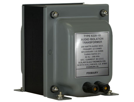
Description
|
SOLAR TRANSFORMERS UPDATE Why the change after all these years? Because you, our valued customers, began requesting data and certificates of calibration for our transformers, which historically we did not provide. The part number changes indicate that we will now provide for each transformer a serial number, a frequency response curve, a correction factor curve for the voltmeter winding, and a certificate of calibration with a five-year calibration cycle. APPLICATION The transformer may also be used In addition, its secondary may be used as an isolating inductor in the power line during transient susceptibility tests. (See Application Note AN622001.) DESCRIPTION Another secondary winding is connected to a pair of binding posts suitable for connecting to AC voltmeter as directed by the applicable EMI specifications. This winding serves to isolate the voltmeter from power ground. Neither the primary nor the secondary windings are connected to the end bells of the core. The transformer may be used as a 4 Ω primary and 1 Ω secondary or 2.4 Ω primary and 0.6 Ω secondary or 2 Ω primary and 0.5 Ω secondary.
|
||||||||||
Specifications
Primary: Less than 5 Ω
Secondary: One-fourth the primary impedance
Frequency response: 30 Hz to 250 kHz
Audio power: 200 W
Dielectric test: 600 V DC primary to secondaries and each winding to end bells
Secondary saturation: 50 A AC or DC maximum
Turns ratio: Two-to-one step down
Secondary inductance: Approximately 1.3 mH (unloaded)
Weight: 18 pounds
Size: 4.5″ wide x 5.25 ” high x 6.25″ deep plus terminals. (11.43 cm x 13.335 cm x 15.875 cm)
Figures
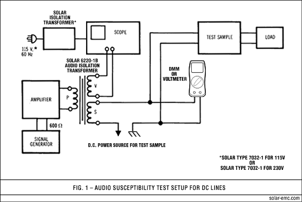
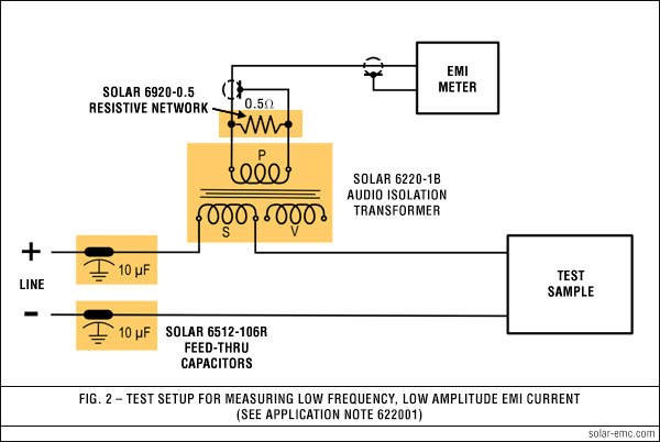
Additional Models
|